SolidWorks README
The full upstream README, mirrored here for reference. Install config, tool schemas, adoption signals, and an original overview live on the SolidWorks listing page.
SolidWorks MCP


Let an AI agent (Claude, or any other MCP client) model real parametric parts and assemblies in your own SolidWorks — and check its own work. Every modelling call returns the measured volume, mass and bounding box, so the agent can compare the result with the spec and correct itself instead of guessing that it "looks about right".
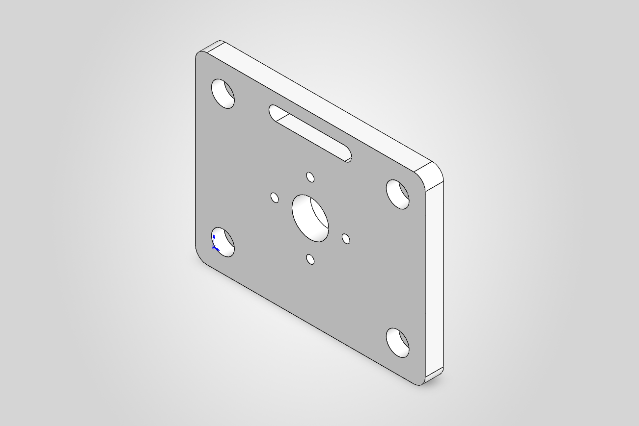
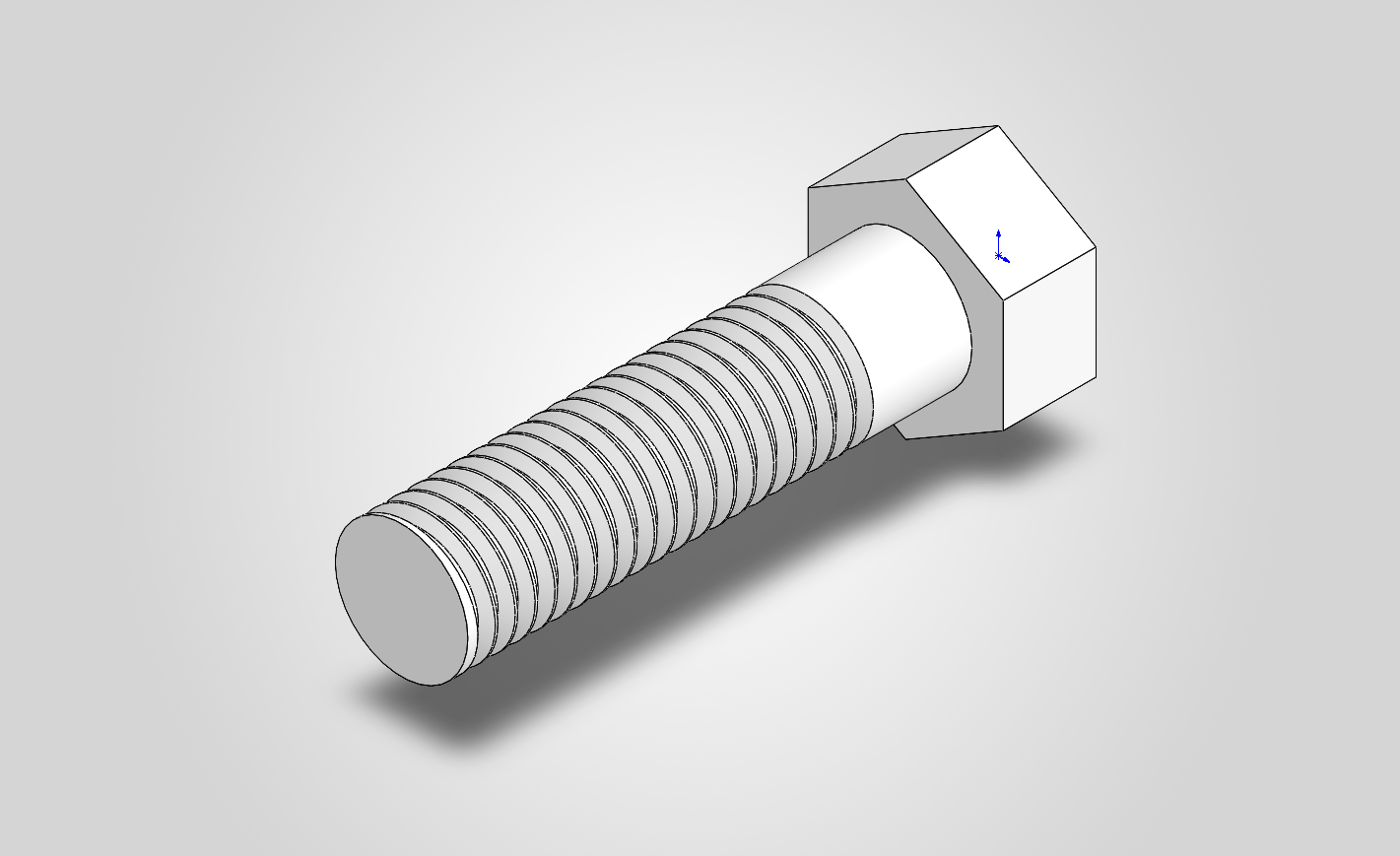
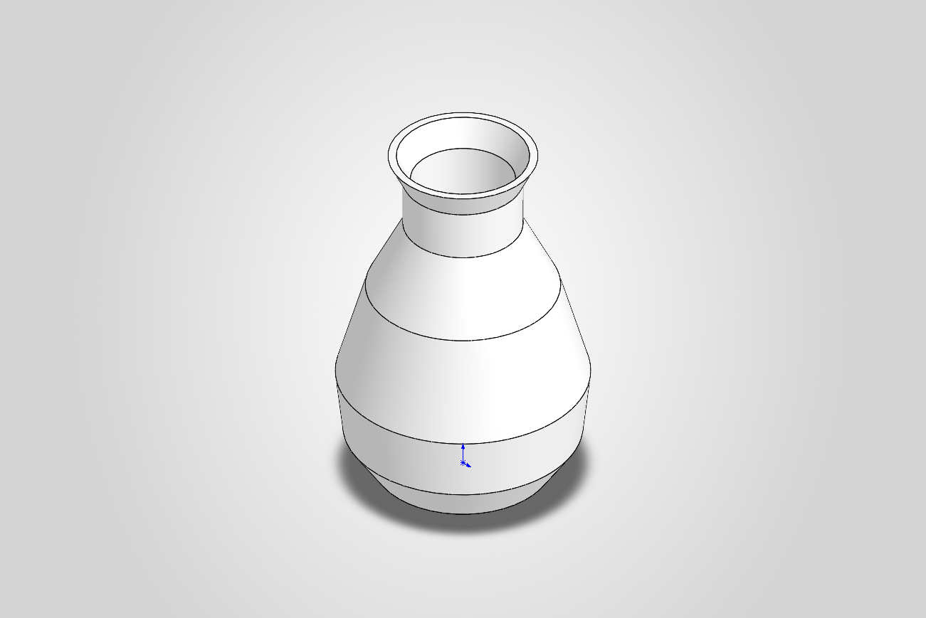
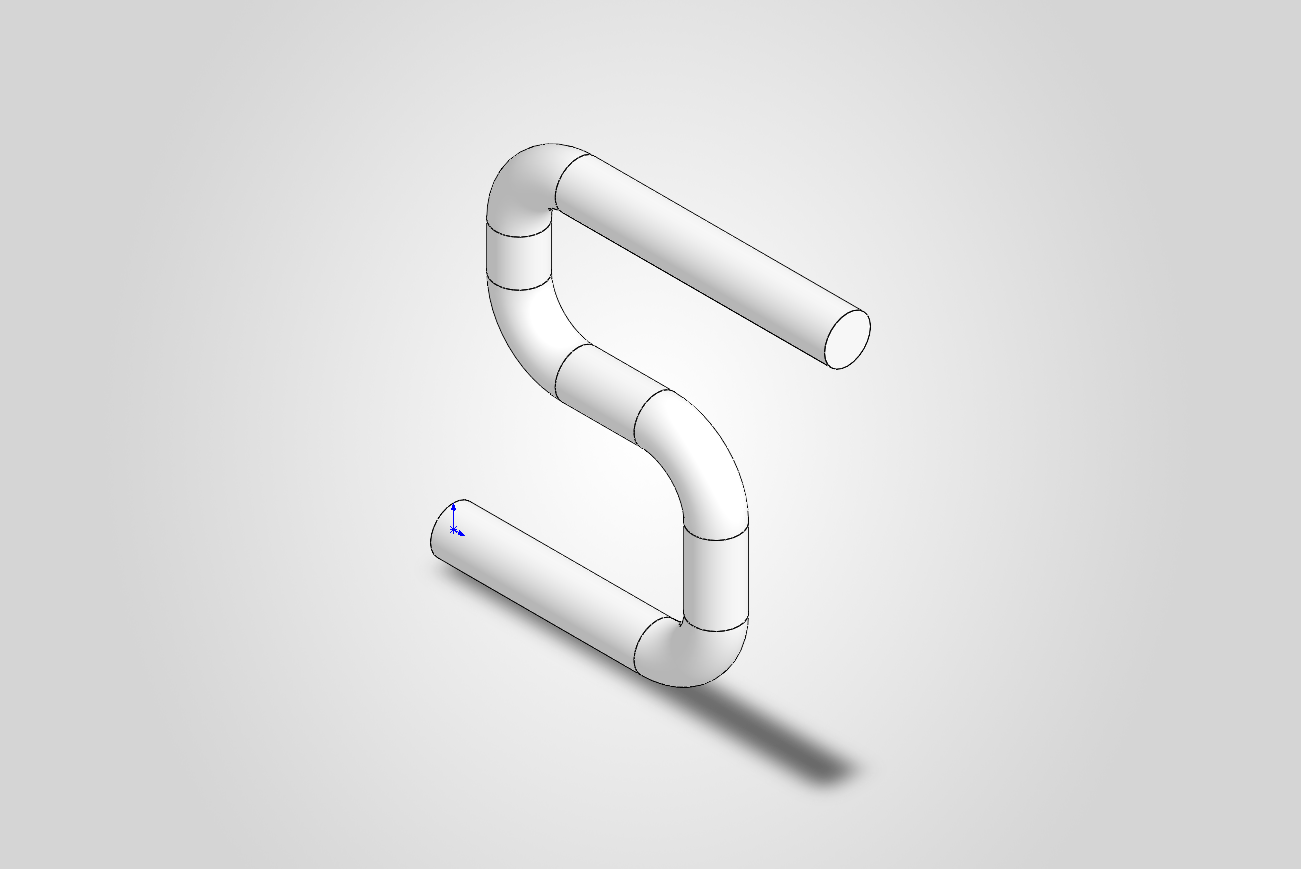
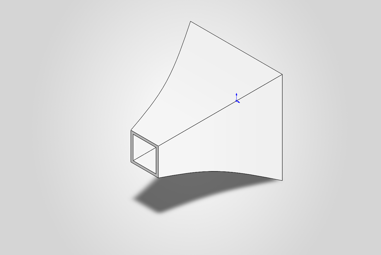
Built by the tools themselves: a mounting bracket (every step checked against a hand calculation), an M10 bolt with a real thread, a revolved + shelled vase, a swept pipe, a lofted + shelled horn.
Why this server
- It verifies, not just generates. Features report measured geometry; dimensions and mates are measured back after the rebuild.
- Fully defined sketches. Every sketch is constrained the way a designer
would: dimensions from the origin, relations only where the geometry is
exactly horizontal, vertical or on the origin. Tools return their dimensions
by role (
width@Sketch1), so the part stays editable, in SolidWorks or through the agent. - Real CAD, not just primitives. Extrude, revolve, sweep, loft and splines; holes, counterbores, slots and pockets on any face; ISO holes from the Hole Wizard; real ISO metric threads; fillets, chamfers, shells, patterns, ribs, equations and materials. Assemblies with mates and interference checks. STEP/STL/3MF export and screenshots. 54 tools in total.
- It fails loud. A call that cannot do what was asked returns
{ok: false, error}with the cause, never silently wrong geometry. - A fixed, typed tool surface. There is no "run arbitrary code" tool; the agent can only do what the tools allow.
- Tested against real SolidWorks. 299 tests; each feature's integration test compares the result with a hand calculation.
- Local. It talks to your running SolidWorks over COM; the server itself makes no network calls.
Quickstart
-
Install uv.
-
Start SolidWorks and leave it open (the server attaches to the running instance — it does not launch one).
-
Register the server with your MCP client.
Claude Code:
Claude Desktop (
claude_desktop_config.json) or any other client:It is also listed in the official MCP Registry as
io.github.hjbaard/solidworks-mcp. -
Ask for a part, for example:
Design a 100 × 80 × 8 mm mounting plate with a Ø16 mm centre bore, four counterbored M5 holes 12 mm from the corners and R5 corners. Check the volume against your own calculation, then export a fine STL.
Guidelines for agents
The server hands every MCP client short modelling guidelines when it connects
(conventions, verify each step, known pitfalls). The full guide is the resource
solidworks://guide: recipes for holes, ribs, threads and assemblies, 3D-print
advice, and how to reverse-engineer a part from a mesh (STL/3MF). The same text
is in src/solidworks_mcp/guide.md.
Requirements and compatibility
- Windows, with SolidWorks installed, licensed and running.
- Python 3.11+ (uv fetches one if needed).
- Tested on SOLIDWORKS 2026 (3DEXPERIENCE R2026x). The API calls it uses exist since SOLIDWORKS 2020 SP2, so 2020–2025 should work, but that is untested. Tried another version? Please open an issue with the result, whether it worked or not.
Status: early (v0.3). It works end-to-end, but tool names and conventions may still change. See CHANGELOG.md.
Troubleshooting
- "No running SolidWorks found" / connection fails — SolidWorks must be
running before you start the server or run a script; it attaches to the active
instance via
GetActiveObjectand does not launch one. - First call is slow or
EnsureModuleerrors — the first COM call generates the makepy typelib wrappers under your tempgen_pyfolder. Let it finish; if it gets into a bad state, delete thegen_pycache and retry. Early binding is mandatory on this build (see Architecture). - A feature returns
{ok: false, error: ...}— that is by design: every tool fails loud with a readable message rather than silently producing wrong geometry. Read the message; it names the likely cause. - Only tested against SOLIDWORKS 2026 (3DEXPERIENCE R2026x). On other builds the
verified enum values or method signatures may differ — re-run
scripts/introspect_api.pyto inspect your installed typelib.
Development
Clone the repository, then install it editable into a venv:
To run the MCP server from this checkout instead of via uvx, point your client at the venv's Python:
Run the verification scripts
With SolidWorks open:
scripts/introspect_api.py regenerates/inspects the installed typelib and prints
verified enum values — run it if SolidWorks is upgraded and signatures change.
Tests
Two layers: pure unit tests (units, selector/direction parsing, polygon
cleaning, the component-placement maths, and that every MCP tool forwards its
arguments to the right session method) run anywhere; integration tests
(solidworks marker) drive a running SolidWorks and verify each feature's
volume — or each component's placement — against a hand calc. They auto-skip if
SolidWorks isn't reachable.
Tools
The server speaks MCP over stdio.
Part tools
| Tool | Purpose |
|---|---|
get_status | Is SolidWorks reachable? revision + active/current part |
new_part | Create a new empty part (becomes current) |
add_box(width_mm, height_mm, depth_mm, name) | Sketch rectangle + extrude; returns mass properties |
add_cylinder(diameter_mm, height_mm, name) | Cylinder by revolving a profile 360° about an axis (Y axis) |
add_disc(diameter_mm, thickness_mm, name) | Disc/puck/flange: circle extruded along +Z (holes/patterns compose) |
add_cone(bottom_diameter_mm, top_diameter_mm, height_mm, name) | Cone/frustum by revolve (top Ø = 0 → full cone) |
add_revolved_profile(profile_mm, angle_deg, name) | Revolve any closed (radius, height) profile about the axis (shafts, vases, rings) |
add_swept_pipe(path_mm, diameter_mm, bend_radius_mm, name) | Sweep a round profile along a 2D path with rounded bends (pipes, tubes, rods) |
add_swept_profile(profile_mm, path_mm, bend_radius_mm, name) | Sweep any closed cross-section along a 2D path (rails, gaskets, trim, channels) |
add_lofted_solid(profiles_mm, heights_mm, name) | Loft/blend 2+ polygon profiles on stacked parallel planes (transitions, adapters) |
add_rib(start_mm, end_mm, toward_mm, thickness_mm, z_mm, name) | Straight rib / gusset in a plane parallel to Front at z_mm, grown toward toward_mm until it meets the part (L-bracket gussets) |
add_extruded_profile(points_mm, depth_mm, name) | Extrude any closed polygon [[x,y],…] (brackets, sections) |
add_extruded_spline(points_mm, depth_mm, name) | Extrude a smooth closed spline through points (free-form/organic outlines) |
add_hole(diameter_mm, x_mm, y_mm, name) | Cut a circular through-hole at (x, y) through the depth axis |
add_counterbore_hole(clearance_diameter_mm, cbore_diameter_mm, cbore_depth_mm, x_mm, y_mm, name) | Counterbored screw hole (flush cap-head / heat-set insert) on +Z |
add_thread(size, x_mm, y_mm, z_mm, length_mm, internal, name) | Real, printable ISO metric thread (e.g. M10x1.5) from a rod's end edge or a hole's mouth, via SolidWorks' Thread feature; the size is checked against the thread profiles. Internal: drill the basic minor diameter first (M10x1.5 → Ø8.376) |
add_hole_on_face(diameter_mm, face, x_mm, y_mm, z_mm, depth_mm, name) | Round hole on ANY planar face at a 3D point, through or blind (side holes, heat-set insert holes); the face through the point is used |
add_hole_wizard(kind, size, face, x_mm, y_mm, z_mm, depth_mm, fit, thread, name) | ISO hole from SolidWorks' Hole Wizard tables: clearance (ISO 273 fits), counterbore, countersink or tapped; thread="modeled" cuts a real, printable thread |
add_boss_on_face(diameter_mm, face, x_mm, y_mm, z_mm, height_mm, name) | Round boss (standoff, peg) grown out of ANY planar face |
add_extruded_profile_on_face(points_mm, face, depth_mm, name) | Polygon pad/ledge grown out of ANY planar face (3D points on the face) |
cut_profile(points_mm, depth_mm, name) | Cut a polygon pocket/slot from the +Z face (blind or through) |
cut_profile_on_face(points_mm, face, depth_mm, name) | Cut a polygon pocket on ANY face (3D points on the face) |
cut_profile_through_plane(points_mm, plane, depth_mm, name) | Cut a polygon drawn on the Front/Top/Right plane, through all both ways or depth_mm centred on the plane (wedges, side windows, symmetric recesses) |
cut_slot(length_mm, width_mm, x_mm, y_mm, angle_deg, depth_mm, name) | Cut a straight slotted hole (obround) on the +Z face at any angle |
add_fillet(radius_mm, edges, name) | Round edges (edges: all, axis x/y/z, or indices "2,5") |
add_chamfer(distance_mm, edges, name) | Chamfer edges at 45° (edges: all, axis, or indices) |
add_shell(thickness_mm, open_face) | Hollow to a wall thickness; open a face (+z/…) or none |
add_linear_pattern(count, spacing_mm, direction, feature_name) | Repeat a feature N times along +x/-x/… |
add_circular_pattern(count, center_x_mm, center_y_mm, feature_name) | Repeat a feature N times around an axis (bolt circle) |
set_dimension(dimension_name, value_mm) | Change a named driving dim (e.g. D1@BlockExtrude, or any name a tool returned in dimensions), rebuild, remeasure |
set_equation(equation) | Add a global equation or variable linking dims (e.g. "W" = 40, then "width@Sketch1" = "W") |
slice_mesh(path, axis, heights_mm, frame) | Cross-sections of an STL/3MF mesh as polygon loops, ready to use as profiles |
compare_with_mesh(path, axis, heights_mm, frame, offset_mm) | Compare the part's cross-sections with a reference mesh (area and extent differences) |
list_dimensions() | Every dimension in the part: name (for set_dimension), feature, value, unit |
set_material(name, database) | Assign a material (e.g. 6061 Alloy) so mass/density are real |
rebuild(top_only) | Force rebuild, report errors |
get_mass_properties | Volume, mass, density, surface area, centre of mass, bounding box |
get_bounding_box | Tight part bounding box (min/max/size, mm) |
list_faces / list_edges | Inspect faces (normal/area/centre) and edges (type/axis/length) by index |
export(path, file_format, quality, deviation_mm, angle_deg) | STEP/STL/IGES/Parasolid/3MF (silent; verifies file). STL/3MF tessellation: quality coarse/fine, or explicit deviation_mm+angle_deg |
screenshot(path) | Isometric, zoom-to-fit PNG/BMP/JPG |
save_part(path) / open_part(path) | Save to / open a native .sldprt |
close_part(save) | Close the current part or assembly |
Assembly tools
| Tool | Purpose |
|---|---|
new_assembly | Create a new empty assembly (becomes the current document) |
open_assembly(path) / save_assembly(path) | Open / save a native .sldasm |
insert_component(path, x_mm, y_mm, z_mm, fixed) | Insert a part with its origin at (x, y, z); the first component is fixed by default |
list_components | Name, path, fixed, position, rotation and bounding box of every component |
set_component_transform(name, x_mm, y_mm, z_mm, rx_deg, ry_deg, rz_deg) | Move/rotate a component; the transform is read back and verified |
add_mate(comp_a, face_a, comp_b, face_b, mate_type, distance_mm, flip) | Mate two planar faces: coincident, distance, parallel, perpendicular — measured back from the geometry afterwards |
check_interference | Component pairs whose solids overlap, with the volume in mm³ (touching faces don't count) |
get_assembly_bounding_box | Bounding box of the whole assembly (min/max/size, mm) |
export and screenshot work on assemblies too.
Faces are selected by direction in the component's own frame (+x, -z, …),
so a selector keeps meaning the same face however the component is turned. Add
:inner (e.g. +y:inner) for the cavity side of a hollow part — the inside of a
room wall instead of its outer skin.
All linear dimensions are millimetres; the server converts to/from the SolidWorks-internal metre/radian units at the boundary.
Architecture
Two non-obvious design decisions, both load-bearing:
-
Early binding is mandatory. On this build
GetActiveObjectreturns a dispatch whoseGetTypeInfo()fails, soEnsureDispatch/CastTocannot infer types and pure late binding breaks (IModelDoc2.FirstFeature→DISP_E_MEMBERNOTFOUND). We generate makepy wrappers from the installed typelib and wrap each raw dispatch in the right interface class; calls then go by dispid viaInvokeTypes, bypassing name resolution. Seebinding.py. -
A dedicated COM thread. COM is STA and thread-affine. The MCP server runs on asyncio, so all COM work is pinned to one worker thread (
com_worker.py) that handlers post to and await — actively enforcing the "one COM session, single-threaded" rule that does not hold automatically in an async server.
Status and roadmap
Proven end-to-end against SOLIDWORKS 2026 (3DEXPERIENCE R2026x):
| Milestone | What it proves | State |
|---|---|---|
| M0 | COM connection to a running SolidWorks | ✅ |
| M1 | new part → sketch rectangle → extrude → mass properties (volume matches hand calc) | ✅ |
| M2 | change a named dimension → rebuild → volume changes predictably | ✅ |
| M3 | full agent loop via the MCP server: build → measure → correct → export STEP/STL + screenshot | ✅ |
| M4 | revolve, sweep, loft, profiles, holes/pockets/counterbores, slots, fillet/chamfer, shell, patterns, equations, materials, save/open | 🚧 ongoing |
| M5 | end-to-end 3D-print part: build a functional mounting bracket through the full loop → verify every dimension → export a fine STL (scripts/m5_demo_bracket.py) | ✅ |
| M6 | assemblies: insert and position components, mate them, check interference — every placement and mate measured back (tests/test_assembly.py) | ✅ |
See Docs/PROGRESS.md for the detailed log and roadmap. Feedback and contributions are welcome.
Known limitations
- Geometry so far: boxes, cylinders/cones (revolve), arbitrary
extruded profiles, holes, polygon pockets/slots (
cut_profile), fillets, chamfers, shells, linear + circular patterns (bolt circles); plus equations, materials, geometry inspection, and save/open of.sldprt, holes + pockets on any planar face (model→sketch transform), round flanges (disc + bore + bolt circle), and slotted holes (cut_slot, obround at any angle — the first arc-based sketch), general revolves (add_revolved_profile: any(r,z)profile → shafts, vases, rings), swept pipes/tubes (add_swept_pipe: a round profile along a rounded 2D path), and lofts (add_lofted_solid: blend stacked polygon profiles → transitions/adapters), free-form extrusions (add_extruded_spline: a smooth closed spline → organic/aesthetic outlines), and non-circular sweeps (add_swept_profile: any cross-section along a path → rails, gaskets, trim). Mirror is shelved — both routes fail on this build; an AI mirrors by placing features symmetrically. - Selection: plane walk, face-by-normal/direction (
_planar_face_by_normal,+z/…, with:innerfor the cavity side of a hollow part), and edge selection by axis or explicit index (_select_edges).list_faces/list_edgeslet an agent inspect geometry before selecting. - Assemblies (M6): components, transforms, mates and interference detection. Component patterns, in-context features, configurations, drawings and Simulation (FEA) are out of scope.