# KiCad Schematics
**Category:** 💻 Developer Tools
**Repository:** https://github.com/unmateria/MCP-Kicad
**Views:** 0
**Installs:** 0
**Upvotes:** 0
**Directory Page:** https://allmcps.com/mcp/kicad-schematics
## Description
Design KiCad schematics by talking to Claude. Places parts, wires nets, runs ERC. Needs KiCad 10.
## Claude Desktop Quick Installation
Heuristic fallback — verify the package name and runner against the repository README before running it. Uses `npx` (confidence: low):
```json
"mcpServers": {
"kicad-schematics": {
"command": "npx",
"args": ["-y","kicad-schematics"]
}
}
```
## Documentation & README
# MCP-KiCad
**Design electronic schematics by talking to Claude.** This is an [MCP](https://modelcontextprotocol.io) server that lets a language model draw real KiCad schematics — placing parts, wiring nets, adding power symbols and running KiCad's own electrical rules check — and hand you a `.kicad_sch` file you can open, edit and manufacture from.
*[Léeme en español](https://github.com/unmateria/MCP-Kicad/blob/HEAD/README.es.md)*
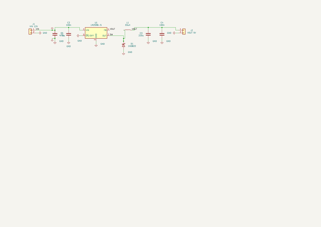
An LM2596 step-down converter. Nobody drew this by hand: it was compiled from a text description, and it passes ERC.
---
## What it actually does
You ask for a circuit in plain language. Claude writes a short declarative description of it and calls one tool, `compile_schematic`, which turns that description into a finished schematic file.
> **You:** Build me a 555 astable running at about 1 Hz, 5 V supply.
>
> **Claude:** *[looks up the real pin names of the NE555, writes the design, compiles it]*
> Done — 7 components, ERC clean. Here's the preview.
The result opens in KiCad like any other schematic. It is not a picture: it is a real file with a real netlist, ready for PCB layout.
### What makes the output usable
Generating *something* is easy; generating a schematic a human would accept is not. Every compiled schematic is checked before you see it, and the compiler refuses to emit anything that fails:
| Guarantee | How it is enforced |
|---|---|
| No wire crosses a wire from a different net | A geometric gate re-checks every segment. Offenders become net labels instead |
| No wire runs through a component body | Same gate, checked against each symbol's real outline |
| Every declared connection exists | The finished file is re-read and its netlist compared against what you asked for |
| No accidental extra connections | The same check, in reverse — a wire that touches a pin it shouldn't is an error |
| Power symbols really touch their pins | Verified by physical contact, not by net name |
| A junction wherever wires meet | The rule was measured across the 115 schematics KiCad ships: a dot where three or more wire ends meet, and where two meet on a pin |
| KiCad agrees | `kicad-cli` runs ERC on the result and the report comes back with it |
If a connection cannot be drawn cleanly, it degrades to a net label rather than producing a wire that lies. **The schematic is never silently wrong.**
A net crossing *itself* is not one of those cases: it is one net either way, so the wire is cut at the crossing and given a junction rather than being thrown away. Only a genuine conflict with another net costs you a wire.
### What it does not do
- **No PCB work.** No board layout, no copper routing, no Gerbers. Schematics only, on purpose — a PCB from a bad schematic is worthless.
- **No component invention.** It uses KiCad's installed symbol libraries, and `find_part` / `import_part` bring in what is missing from external KiCad libraries — verified before installation. If a part exists nowhere, it says so instead of drawing one.
- **Not a simulator.** It draws what you describe; it does not tell you whether your circuit is a good idea.
---
## Requirements
| | |
|---|---|
| **KiCad 10** | Provides `kicad-cli`, used for ERC and for rendering. Earlier versions are untested. |
| **Claude Desktop** or **Claude Code** | Or any other MCP client. |
| **Go 1.24+** | Only if you build from source. |
---
## Installation
### Option A — one click (recommended)
Download **`mcp-kicad.mcpb`** from [**Releases**](https://github.com/unmateria/MCP-Kicad/releases/latest) and double-click it. Claude Desktop installs it as an extension: no JSON to edit, no paths to type. The bundle carries the Windows, macOS and Linux builds, so the same file works everywhere.
Then skip straight to [Checking that it works](#checking-that-it-works).
> On Apple Silicon the bundled macOS build runs through Rosetta. If you want the native one, take `mcp-kicad-darwin-arm64` from Option B instead.
### Option B — download a binary
1. Go to [**Releases**](https://github.com/unmateria/MCP-Kicad/releases) and download the file for your system:
| System | File |
|---|---|
| Windows (Intel/AMD) | `mcp-kicad-windows-amd64.exe` |
| Linux (Intel/AMD) | `mcp-kicad-linux-amd64` |
| Linux (ARM, e.g. Raspberry Pi) | `mcp-kicad-linux-arm64` |
| macOS (Apple Silicon) | `mcp-kicad-darwin-arm64` |
| macOS (Intel) | `mcp-kicad-darwin-amd64` |
2. Put it wherever you like — say `C:\Tools\mcp-kicad.exe` or `~/bin/mcp-kicad`.
3. On Linux and macOS, make it executable:
```bash
chmod +x ~/bin/mcp-kicad
```
On macOS the first run is blocked because the binary is unsigned. Allow it with:
```bash
xattr -d com.apple.quarantine ~/bin/mcp-kicad
```
There is nothing else to install. The binary is self-contained and needs no configuration file: it finds KiCad on its own.
### Option C — build from source
```bash
git clone https://github.com/unmateria/MCP-Kicad.git
cd MCP-Kicad
go build -o mcp-kicad ./cmd/server # add .exe on Windows
```
---
## Connecting it to Claude
*Not needed if you installed the `.mcpb` bundle — it registers itself.*
### Claude Desktop
Edit the configuration file — create it if it isn't there:
| System | Location |
|---|---|
| Windows | `%APPDATA%\Claude\claude_desktop_config.json` |
| macOS | `~/Library/Application Support/Claude/claude_desktop_config.json` |
| Linux | `~/.config/Claude/claude_desktop_config.json` |
Add the server:
```json
{
"mcpServers": {
"kicad": {
"command": "C:\\Tools\\mcp-kicad.exe",
"args": []
}
}
}
```
On Linux or macOS the command is a normal path, `"/home/you/bin/mcp-kicad"`.
> **Windows note:** backslashes must be doubled in JSON (`C:\\Tools\\...`). A single backslash is the single most common reason the server fails to start.
**Then quit Claude Desktop completely and reopen it.** Reloading the window is not enough — the server runs as a child process and only starts on a full restart.
### Claude Code
```bash
claude mcp add kicad -- /path/to/mcp-kicad
```
### Checking that it works
Ask Claude:
> Use get_project_info to check the KiCad setup.
You should get back the detected `kicad-cli` path, the library directories, and the output directory. If it reports that `kicad-cli` was not found, see [Configuration](#configuration) below.
---
## Using it
Just describe the circuit. Be specific about what matters to you — supply voltage, part numbers you want, values you've already chosen — and leave the rest to Claude.
Prompts that work well:
> Design a 5 V regulated supply from a 12 V input using an LM7805, with input and output decoupling and a power LED.
> Make me an ATmega328P minimal board: 16 MHz crystal with load caps, reset pull-up, ICSP header, and decoupling on both supply pins.
> Build a two-transistor astable multivibrator that blinks two LEDs at roughly 2 Hz.
Useful things to ask for afterwards:
- *"Show me the schematic"* — renders a preview image.
- *"Export it as PDF"* — through `kicad-cli`.
- *"Run ERC"* — KiCad's electrical rules check, with the violations explained.
- *"Move the decoupling caps closer to U1 and recompile"* — the design source is text, so revisions are cheap.
The generated files land in the output directory (`get_output_dir` tells you where; `set_output_dir` changes it).
### The design source
Behind the scenes, Claude writes a small JSON document and compiles it. You will rarely need to touch this, but it is worth seeing, because it explains why the results are stable — **positions are never given in millimetres, they are anchored pin-to-pin**:
```json
{
"version": 1,
"project": "led_18650",
"sheet": "auto",
"blocks": [
{
"name": "led",
"symbols": [
{ "ref": "BT1", "lib": "Device:Battery_Cell", "value": "18650" },
{ "ref": "R1", "lib": "Device:R", "value": "100", "rot": 90,
"place": { "pin": "1", "at": "BT1.+", "dir": "up", "cells": 1 } },
{ "ref": "D1", "lib": "Device:LED", "value": "LED_RED", "rot": 90,
"place": { "pin": "A", "at": "R1.2", "dir": "right", "cells": 3 } }
]
}
],
"nets": {
"VBAT": ["BT1.+", "R1.1"],
"_ANODE": ["R1.2", "D1.A"],
"GND": ["D1.K", "BT1.-"]
},
"power_nets": { "GND": "power:GND" }
}
```
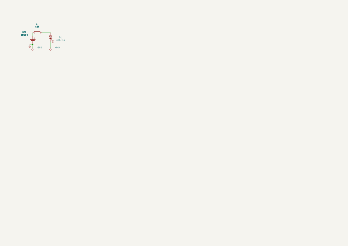
The first symbol in a block anchors it; every other symbol hangs off a pin of one already placed, a whole number of 2.54 mm grid cells away. That is how a schematic stays on-grid and readable no matter how the model reorders things.
The complete format is specified in [`internal/tools/design_format.md`](https://github.com/unmateria/MCP-Kicad/blob/HEAD/internal/tools/design_format.md) (the same text the `design_guide` tool serves to the model), and there are thirteen worked examples in [`docs/compiler/`](https://github.com/unmateria/MCP-Kicad/blob/HEAD/docs/compiler/) — from a two-part LED circuit to a greenhouse controller with 27 components.
---
## Configuration
None is required. The server looks for KiCad in the usual places:
- **Windows** — `C:\Program Files\KiCad\\bin\kicad-cli.exe`, then `PATH`
- **Linux** — `/usr/bin/kicad-cli`, `/usr/local/bin/kicad-cli`, then `PATH`
- **macOS** — `/Applications/KiCad/KiCad.app/Contents/MacOS/kicad-cli`, then `PATH`
If your install is somewhere unusual, or you want to change where files are written, copy `config.ini.example` to `config.ini` **next to the executable** and fill in what you need:
```ini
[paths]
kicad_cli = /opt/kicad/bin/kicad-cli
output_dir = /home/you/schematics
libs_root = /home/you/mcp-kicad-libs
[api_keys]
mouser =
digikey_client_id =
digikey_client_secret =
```
The API keys are optional and buy metadata only — no distributor serves CAD
files. Every source that actually carries symbols and footprints needs no key.
Generated files default to `/mcp-kicad/output`.
---
## Tools
Thirty-three tools are exposed. In practice Claude drives almost everything through `compile_schematic`; the rest exist for inspection and for repairing an existing file.
**Designing**
`compile_schematic` · `design_guide` · `get_design_context` · `kicad_workflow_help` · `apply_template` · `list_templates`
**Finding parts**
`find_part` · `import_part` · `check_component_existence` · `symbol_pins` · `list_symbol_libraries` · `register_library`
**Reading a schematic**
`read_schematic` · `get_connectivity_summary` · `cluster_components` · `layout_metrics`
**Editing by hand**
`create_schematic` · `add_symbol` · `connect_pins` · `disconnect_pin` · `add_wire` · `add_label` · `add_power_rail` · `junction` · `no_connect` · `connect_netlist` · `batch_schematic`
**Checking and exporting**
`validate_design` (ERC/DRC) · `export_schematic_image` (SVG/PDF) · `modify_pcb_layout`
**Setup**
`get_project_info` · `get_output_dir` · `set_output_dir`
---
## Parts KiCad doesn't have
KiCad ships around 22 700 symbols. The one you need is often not among them.
`find_part` searches every source at once and `import_part` installs a
candidate:
```
find_part query="ESP32-C3-MINI-1"
import_part ref="espressif:symbols/Espressif.kicad_sym#ESP32-C3-MINI-1"
→ MCP_Imported:ESP32-C3-MINI-1 53 pins, footprint matched, ready for compile_schematic
```
| Source | What it carries | Licence |
|---|---|---|
| *installed* | this machine's KiCad libraries and everything already imported | — |
| **jlcpcb** | JLCPCB's assembly catalogue: symbol + footprint + 3D model, all matched | MIT |
| **cern** | CERN Open Hardware: symbols for thousands of real part numbers | CERN-OHL-P-2.0 |
| **digikey-lib** | Digi-Key's library, 150 category libraries | per repository |
| **espressif** | Espressif's own ESP32 library | per repository |
| **sparkfun** | SparkFun breakouts, sensors and connectors | CC-SA-4.0 |
| **lcsc** | LCSC / EasyEDA, converted to KiCad — the long tail, by C-number | third-party data |
| **mouser**, **digikey** | identification only: the real MPN, manufacturer, package and datasheet behind an order code. **No CAD files** — no distributor serves them. Needs an API key | — |
Each source is indexed once into `libs/cache/` and searched offline from then
on. Nothing is installed until it has been verified:
1. it parses,
2. `kicad-cli` reads it back and rewrites it,
3. it places in a scratch schematic with its pins resolved,
4. its pins are compared against the footprint's pads,
5. KiCad draws it, and you get the picture.
**A part that fails is not installed at all.** A half-imported symbol is worse
than no symbol, because it looks like it works. And if a part exists in no
source, the answer is that it does not exist — never a substitute chosen
quietly, never geometry drawn from imagination.
Everything lands in one library, `MCP_Imported`, registered with KiCad so the
GUI's symbol chooser sees it too. Each imported symbol carries an `MCP_Source`
property recording where it came from, under what licence and when — which is
why `libs/` is not versioned: it is reproducible from the sources.
---
## How it works
`.design.json` → **compile** → `.kicad_sch`
1. **Place.** Every symbol's position is derived from a pin anchor, resolved to absolute coordinates on the 2.54 mm grid.
2. **Wire.** Short, obviously-correct connections are drawn with closed-form geometry; longer ones go to an A\* router that avoids component bodies.
3. **Power.** One power symbol per pin, offset in the direction the pin points, then aligned into rails.
4. **Gate.** Every wire is re-examined. Anything that crosses another net, cuts through a symbol or overlaps collinearly is deleted and replaced by net labels — connectivity is preserved, the lie is not.
5. **Tidy.** Reference and value text is moved off bodies and wires; the sheet is centred and the paper size upgraded if the circuit doesn't fit.
6. **Verify.** The file is re-read from scratch, its netlist traced and compared against the source, and `kicad-cli` runs ERC.
KiCad files are read and written through a real S-expression parser ([`internal/sexp`](https://github.com/unmateria/MCP-Kicad/blob/HEAD/internal/sexp)) — never by pattern-matching on text.
---
## Known limitations
- **Text can still overlap on dense sheets.** Reference designators and net labels are moved to the lowest-overlap position available, but on a crowded schematic the best available spot sometimes still touches something. The compiler reports exactly what is left over and how much extra spacing would clear each one.
- **Some connections become labels instead of wires.** This is the gate doing its job. Electrically identical, less pretty.
- **PNG previews need a Chromium-family browser** (Edge, Chrome, Chromium or Brave). Without one, a lower-quality pure-Go renderer is used instead. Only the Windows path is verified in practice.
- **Tested with Claude Desktop and Claude Code.** Other MCP clients should work but haven't been tried.
---
## Development
```bash
go build -o mcp-kicad ./cmd/server # build
go test ./... # all tests
go run ./cmd/verify_e2e # end-to-end smoke test
go run ./cmd/compile -o out.kicad_sch docs/compiler/led_18650.design.json
go run ./cmd/measure_layout out.kicad_sch # layout quality metrics
go run ./cmd/pininfo # pin positions in a symbol library
# The component sources are claims about the outside world. `go test ./...`
# never touches the network; these re-measure them on demand.
MCP_KICAD_LIVE=1 go test ./internal/parts/providers/ -run TestLive -v
MCP_KICAD_LIVE=1 go test ./internal/tools/ -run TestLiveImportAndCompile -v
```
The thirteen sources in `docs/compiler/` are the reference corpus — every change to the pipeline is checked against all of them.
Architecture notes live in [`CLAUDE.md`](https://github.com/unmateria/MCP-Kicad/blob/HEAD/CLAUDE.md).
---
## License
[PolyForm Noncommercial License 1.0.0](https://github.com/unmateria/MCP-Kicad/blob/HEAD/LICENSE.md) — free to use, modify and share for any **noncommercial** purpose, including personal projects, hobby electronics, education, research and nonprofit organisations. Commercial use is not granted by this license.